Technical Education
pH
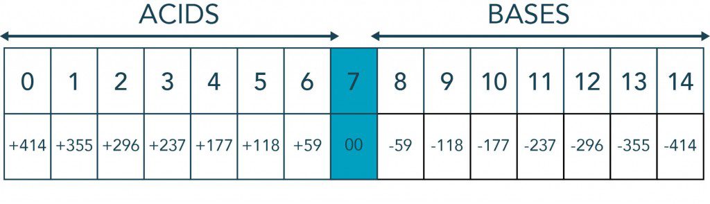
One of the most widely used water measurements, pH is a measure of acidity and alkalinity, or caustic and base, respectively, of a solution. It is expressed typically on a numeric scale of 0-14. A value of 7 represents neutrality. Lower numbers indicate increasing acidity and higher numbers increasing alkalinity. Each unit of change represents a tenfold change in acidity or alkalinity which corresponds to the negative logarithm of the hydrogen-ion concentration or hydrogen-ion activity.
H2O -> H+ + OH- = 1 x 10-14 (mol/L)2 = Kw
Hydrogen Ion Concentration in Moles/Liter at 25° C
| pH | H+ conc. | OH – conc. |
| 0 | 1.0 | 0.00000000000001 |
| 1 | 0.1 | 0.0000000000001 |
| 2 | 0.01 | 0.000000000001 |
| 3 | 0.001 | 0.00000000001 |
| 4 | 0.0001 | 0.0000000001 |
| 5 | 0.00001 | 0.000000001 |
| 6 | 0.000001 | 0.00000001 |
| 7 | 0.0000001 | 0.0000001 |
| 8 | 0.00000001 | 0.0000001 |
| 9 | 0.000000001 | 0.00001 |
| 10 | 0.0000000001 | 0.0001 |
| 11 | 0.00000000001 | 0.001 |
| 12 | 0.000000000001 | 0.01 |
| 13 | 0.0000000000001 | 0.1 |
| 14 | 0.00000000000001 | 1.0 |
Why is pH an Important Measurement?
It determines product quality in:
- Sugar refining
- Pulp and paper mills
- Latex coagulation
- Photo developing
It enhances product efficiency of:
- Flue gas scrubbing
- Circuit board etching
- Fermentation processing
- Assuring product safety
- Chromate and cyanide destruct systems
- Potable and waste waters
- Food, low pH to prevent botulism
How Can pH be Measured?
Colorimetric Methods
- Reagent addition
- pH paper
Electrochemical Methods (pH electrodes)
A pH Measuring System Consists of:
- A pH electrode: an electrode whose output voltage changes as the pH (hydrogen ion concentration) changes.
- A reference electrode: an electrode whose voltage output stays constant.
- A pH meter: a millivolt meter with a special high impedance input circuit and circuits to change the electrode’s millivolts into pH unit readouts.
- Optionally, an automatic temperature compensator: a device which senses temperature so that the meter can correct for the effects of temperature changes.
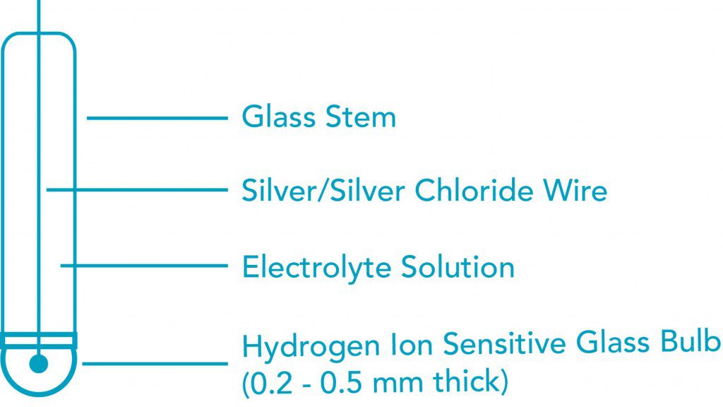
How Does A pH Electrode Work?
- Special composition glass senses H+ and a millivoltage is generated (59.2 mV per pH unit at 25° C).
- A filling solution picks up the signal from the special pH glass.
- A pure silver wire dipped in silver chloride passes the signal from the solution whose pH is being measured to the electrode’s cable or connector.
- Sodium Ion error for solutions > pH 12.3.
How Does A Reference Electrode Work?
- A porous reference junction separates the filling solution in the electrode from the solution whose pH is to be measured.
- The filling solution’s constant chloride ion concentration generates a millivoltage at a pure silver wire with silver chloride on it.
- The silver wire passes the signal from the solution being measured to the electrode’s cable or connector.
Single vs. Double Junction Reference
Chemicals that cause silver to precipitate at the reference junction will contaminate and plug single junctions. These may be such compounds as sulfides, mercaptans, cyanides, Iodides, and proteins. Other compounds such as silver, lead, mercury, and other heavy metal compounds will react with the chloride in the gel, causing a reduction in the reference output. Selection of the proper chemistry in the lower (double) junction will prevent or at least minimize the negative effects of these reactive compounds.
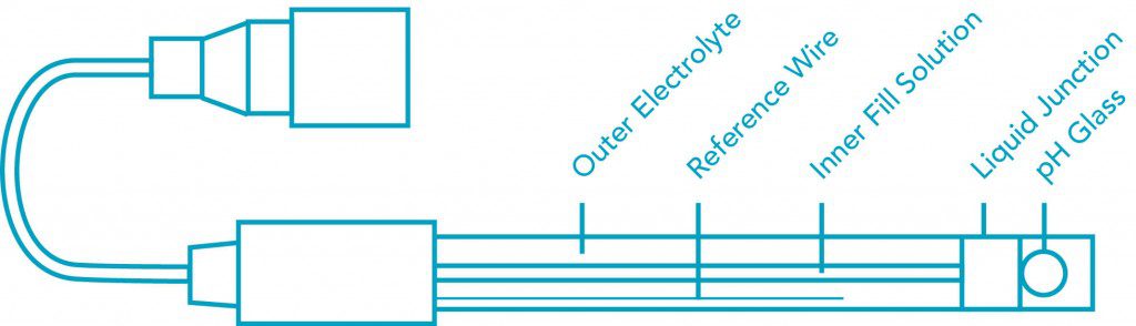
How Does A Combination pH Electrode Work?
A combination pH electrode consists of a pH electrode and a reference electrode built into a single body or housing. A combination electrode therefore works like the pH and reference electrodes combined!
How Does a pH Meter Work?
A pH meter takes the input from the pH glass (high impedance mV) and the input from the reference sensor and compares these two values to get a resulting millivolt reading. The reading in mV is converted to pH by the following guidleine:
- Zero mV = pH 7
- 59.2mV per pH unit change
- mV are + for pH <7 and mV are – for pH >7
Example of a pH Circuit
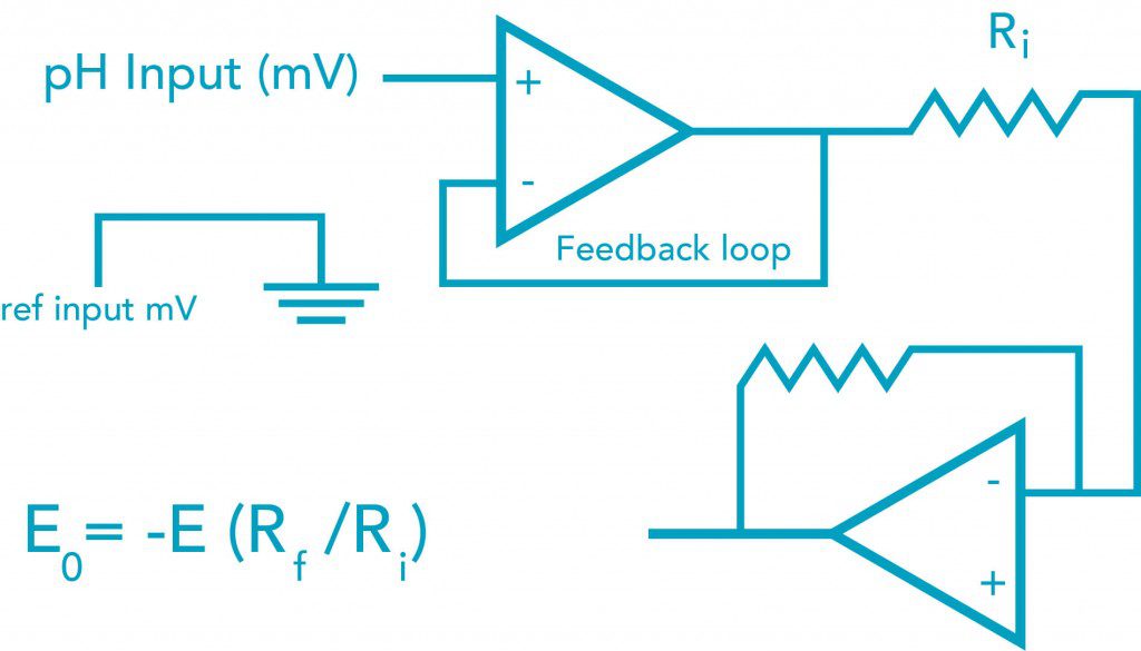
Note that the pH and reference input go into an operational amplifier (op amp) due to the very high resistance of the pH glass. The meter will also adjust zero and span offsets and can do automatic temperature compensation for pH error (discussed below).
Temperature Compensation
When measuring pH using a pH electrode the temperature error from the electrode varies based on the Nernst Equation as 0.03pH/10C/unit of pH away from pH7. As shown in the table below, the error due to temperature is a function of both temperature and the pH being measured. Note that there is no error at pH7 and 25° C. Temperature compensation can be achieved manually or automatically. Manual temperature compensation is usually achieved by entering the temperature of the fluid being measured into the instruments menu and then the instrument will display a “Temperature Compensated” pH reading. This means that the pH value is corrected to the value expected at 25° C. Automatic temperature compensation requires input from a temperature sensor and constantly sends a compensated pH signal to the display. Automatic temperature compensation is useful for measuring pH in systems with wide variations in temperature.
| pH 2 | pH 3 | pH 4 | pH 5 | pH 6 | pH 7 | pH 8 | pH 9 | pH 10 | pH 11 | pH 12 | |
| 5° | .30 | .24 | .18 | .12 | .06 | 0 | .06 | .12 | .18 | .24 | .30 |
| 15° | .15 | .12 | .09 | .06 | .03 | 0 | .03 | .06 | .09 | .12 | .15 |
| 25° | 0 | 0 | 0 | 0 | 0 | 0 | 0 | 0 | 0 | 0 | 0 |
| 35° | .15 | .12 | .09 | .06 | .03 | 0 | .03 | .06 | .09 | .12 | .15 |
| 45° | .30 | .24 | .18 | .12 | .06 | 0 | .06 | .12 | .18 | .24 | .30 |
| 55° | .45 | .36 | .27 | .18 | .09 | 0 | .09 | .18 | .27 | .36 | .45 |
| 65° | .60 | .48 | .36 | .24 | .12 | 0 | .12 | .24 | .36 | .48 | .60 |
| 75° | .75 | .60 | .45 | .30 | .15 | 0 | .15 | .30 | .45 | .60 | .75 |
| 85° | .90 | .72 | .54 | .36 | .18 | 0 | .18 | .36 | .54 | .72 | .90 |
Note: Values in light blue are less than 0.1 error and may not require temperature compensation. Values in dark blue are temperature and pH in which there is no error in pH from temperature.
How are pH Systems Calibrated?
- The electrodes are placed in buffers. Buffers are solutions of known, stable pH value
The commonly used buffers have pH values of 4.01, 7.00 and 10.00
The pH values of buffers change with changes of temperature (and so does the pH of solutions being measured) - First the the system’s (electrode and meter together) Zero Point is adjusted
Zero point is usually determined with pH 7.00 buffer
Ideally, a buffer is used whose value is close to that of the material or solution being measured
A “calibrate “or “standardize” adjustment potentiometer knob or push button on the pH meter is used to set the system (electrode and meter together) to read the buffer’s pH value - Next, the system’s span is checked and/or adjusted. The electrodes are rinsed and put into a second buffer
The system should read close to the pH value of the second buffer.
Most meters have controls labeled “SPAN” or “SLOPE” which compensates for electrodes with spans that are too short. - The frequency of calibration is at the discretion of the user.
- NOTE: Two-point calibration is necessary to ensure electrode works properly since a broken electrode can give acceptable pH7 output in calibration mode.
pH Applications
- Wastewater neutralization
- Electroplating
- Chemical manufacturing
- Circuit board etching
- Flue gas scrubbers
- Boilers and cooling towers
- Pulp and paper mfg.
- Food and beverage
- Pharmaceuticals
- Inks, paints latex
- Water treatment (sewage)
- Aquariums, aquaculture
- Fermentation (wine, beer, alcohol)
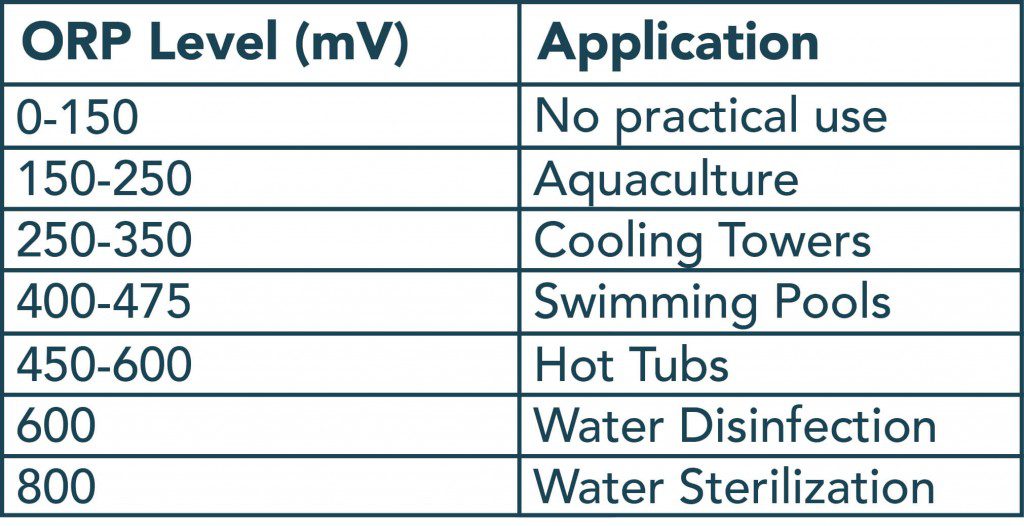
ORP
ORP is an abbreviation for for Oxidation Reduction Potential, also know as REDOX, and is a useful measurement for monitoring and controlling chemical reactions.
- Oxidation: addition of oxygen/reduction of electrons
- Reduction: reduction of oxygen/addition of electrons
Characterisitics of ORP:
- Non-specific measurement of total activity
- mV output allows automated control of chemical reactions
Typical examples of ORP uses include:
- Ozone or chlorine control
- Chromate reduction or cyanide destruction
Units of Measure for ORP = mV
ORP MEASURING ELECTRODES
An ORP measuring electrode is identical to pH measuring electrodes except a nobel metal is used in place of the pH glass as the measuring element. Noble metals are used because they will not enter into the chemical reaction taking place. Other nobel metals such as gold or silver can be used but platinum is the most commonly used.
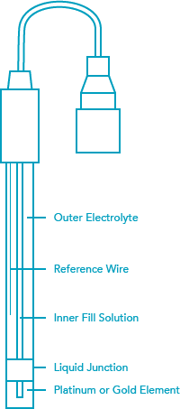
The reference is identical to the one used in the pH electrode. It is a Ag/AgCl (silver/silver chloride) wire in 3.5M KCl saturated with AgCl (silver chloride). A second junction for protection of the reference wire is common in industrial electrodes and is referred to as a “Double Junction”. A combination ORP electrode works the same as a combination pH electrode. The measuring electrode generates a millivolt output based on the oxidizing or reducing reactions taking place while the reference electrode generates a constant millivolt output. The working range of an ORP electrode is +/- 2000mV. A pH meter with a millivolt scale or ORP transmitter or controller is used to display readings.
Temperature compensation is not used for ORP measurements. The correction factors are system and chemical dependent and are not easily determined.
Examples of ORP vs. various Oxidizing Agents
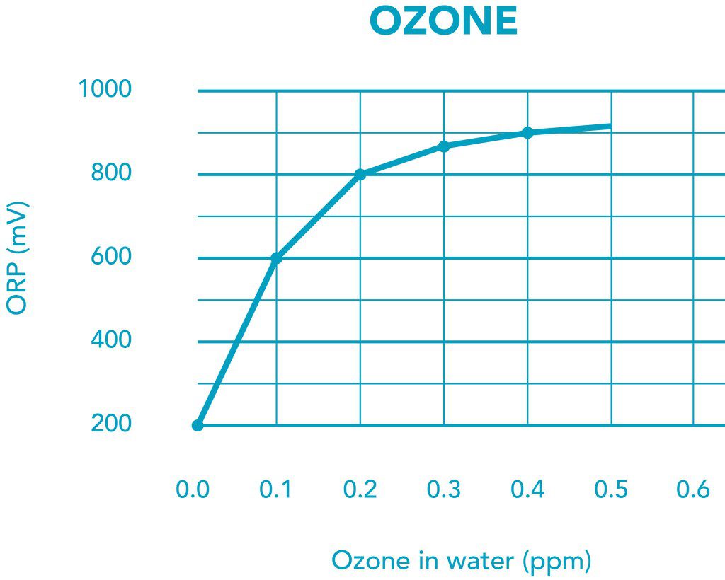
ORP mV vs. Ozone ppm
| ORP mv | APPLICATION | OZONE ppm |
| 200-400 | Aquaculture, cooling towers | <0.06 |
| 500-600 | Swimming pools, hot tubes | <0.15 |
| 600-800 | Water disinfection | <0.4 |
| 800+ | Water sterilization | >0.4 |
ORP Applications
- Water treatment (sewage) – prechlorination and dechlorination
- Metal Finishing (CN destruct and chromate reduction)
- Ozone treatment (Commercial Aquariums, water disinfection)
- Bleach production
- Poultry processing – disinfect the skin
- Fruit and vegetable washing
- Pulp bleaching (paper industry)
- Chlorine addition (swimming pools, spas)
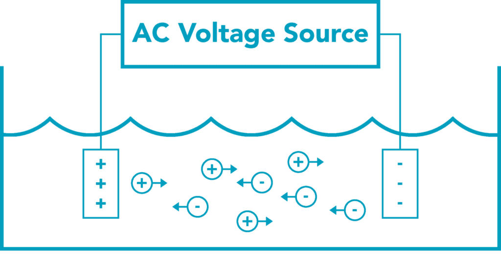
CONDUCTIVITY
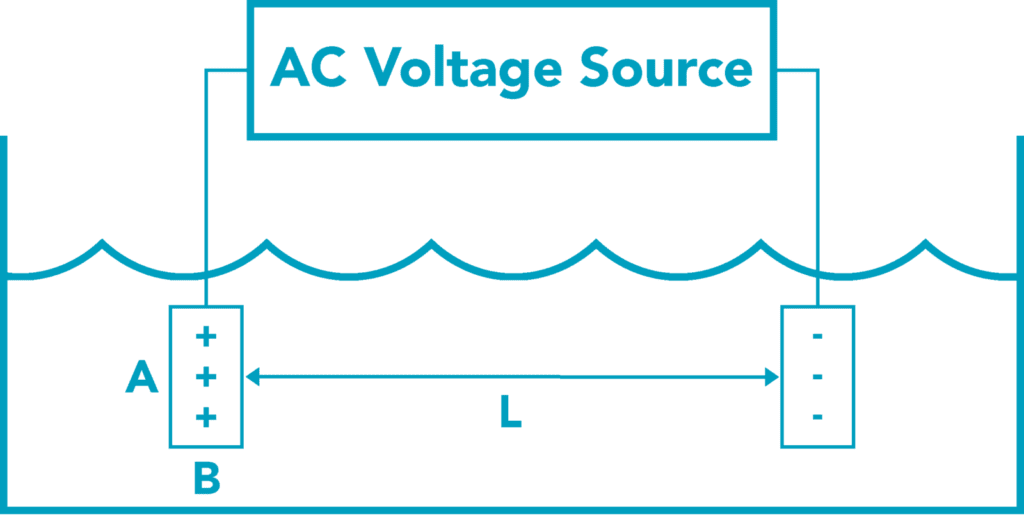
Conductivity is a measurement of the ability of a solution to conduct an electric current. An instrument measures conductivity by placing two plates of conductive material with known area and distance apart in a sample. Then a voltage potential is applied and the resulting current is measured.
Using Ohms Law, V= iR and knowing conductivity G= 1/R then G can be determined as
G= 1/R = i/V
The number of ions that are conductive, metals, salts, etc, provides the conductive path between two electrodes of the conductivity cell. Higher ionic concentration yields higher conductivity. Typically an AC signal is used to prevent ionization of the electrodes.
Temperature effects and compensation:
Increasing temperatures can make the ions in the water move faster. Conductivity levels falsely increase approximately 2% per °C — more for resistive waters (up to 4 or 5% per °C )
TERMINOLOGY
The Terminology used to express a unit of electrical conductance is a microSiemen (Formerly a micromho). High conductivity values can be expressed as milliSiemens.
Below 1 microSiemen, we express units of measure as ohms of resistance rather than fractions or decimals of conductance.
- 1 micromho = 1 microSiemen
- 1,000,000 ohms = 1 megaohm.
- 1/1,000,000 ohms is = microSiemen
- 1000 micromhos = 1000 microSiemens = 1 milliSiemen.
Many years ago, the water treatment industry adopted a nomenclature of PPM. Correlating PPM to microSiemens can be difficult, as water can be make up of different salt concentrations and dissolved metals, which can alter the conversion factor. It is preferable to use microSiemens as a unit of measure; however, if you need to convert to PPM, you can use the following formula:
- 1 ppm = 1.5 microSiemen.
- 1 ppm (sodium chloride) ˜ 2 micro siemens (<30,000 uS).
- 1ppm (mixed salts) ˜ 1.5 micro siemens (<1,000 uS).
A more exact conversion factor is:
Cell Constant (K) Values
Cell constants define the volume between the electrodes. Cell constant k is directly proportional to the distance separating the two conductive plates and inversely proportional to their surface area. K = L/a, where a(area) = A x B.
Materials of Construction
The basic conductivity probe is comprised of two conductive surfaces separated by a given distance in a body. The body material can be anything from PVC, CPVC, PVDF, PTFE, PEEK, or even stainless steel. The measuring surfaces (usually pin configuration) are typically constructed of graphite, stainless steel, titanium, or platinum. The basic criteria for determining which is best are based on cost and performance requirements.
CLEANING & MAINTENANCE
Some care should be taken when cleaning conductivity probes. Scratches and abrasions on the surface of the pins increase the surface area which alters the cell constant and provides a retention area for old samples, causing calibration and measurement difficulties. Graphite being a soft material is most susceptible. Cleaning should be done with chemicals and soft non-abrasive cloths. Sanding is not recommended. HCL is an excellent material to dissolve many coatings.
ALTERNATE TECHNOLOGIES
The basic two-pin conductivity cell is all we have discussed to this point. There is four-pin technology that tries to better control the field surrounding the conductivity sensor to improve stability. These are known as contacting type conductivity cells.
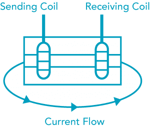
Another type of technology is the non-contacting (Toroidal) cell, which uses a magnetic field to sense conductivity. A transmitting coil generates a magnetic alternating field that induces an electric voltage in a liquid. The ions present in the liquid enable a current flow that increases with increasing ion concentration. The ionic concentration is then proportional to the conductivity. The current in the liquid generates a magnetic alternating field in the receiving coil. The resulting current induced in the receiving coil is measured and used to determine the conductivity value of the solution. Advantages to this type of cell are:
- No polarization
- Reduced maintenance and resistance to chemical attack
- Complete galvanic separation of measurement from medium (eliminates ground loss)
CONDUCTIVITY APPLICATIONS
Generation:
- Flue gas scrubbers
- Foods:
- Brines – concentration
- Sugar: First carbonation
- Clean-in-place (CIP) applications
- Saturation control
- Cooker control
- Desalting of food products
- Cheese souring
- Evaporation control – dried milk, etc.
- Glucose
- Lye peeling of fruits and vegetables
- Rinsing water
- Waste water; and
- Pickle making
Streams and Lake Water:
- Water pollution
- Salt intrusion
Chemicals:
- Sulfuric acid and oleum
- Chlorine-alkali plants
- Sodium chloride, sodium hydroxide
- Hydrochloric acid
- Superphosphate
- Phosphoric acid
- Nitric acid
- Glycerine
- Fertilizer
- Detergents
- Waste water
- Moisture detection in HF
- Scrubbers
Textiles:
- Water quality surveys
- Scouring baths
- Rinsing water
- Carbonizing baths
- Mercerizing baths
- Boiler water systems; and
- Acid washing.
Metals and Mining:
- Caustic/Alumina ration control
- Continuous steel pickling
- Plating solution monitoring/control
- Alkaline/caustic metal cleaning process
- Copper flotation
- Heavy metal recovery
Pulp and Paper:
- White liquor
- Cooking liquor
- Black liquor
- Green liquor
- Weak wash liquor
- Brown stock washing
- Steam generation
- Heat exchangers
- Waste water; and
- Cl2/ ClO2 scrubbers.
Water Treatment:
- Ion exchangers
- Regeneration monitors
- Reverse osmosis
- Reverse osmosis
- Scrubbing towers (HCl gas in water)
- Softener regeneration.
Processing:
- Interface monitoring and control
- Leak detection
- HF alkylation
- Scrubbers
Hydrocarbon:
- Oil well drilling (mud and sediment)
Steam:
- Boiler blow down
DISSOLVED OXYGEN
Dissolved Oxygen (DO) is the term used for the measurement of the amount of oxygen dissolved in a unit volume of water. In water quality applications, such as aquaculture (including fish farming) and waste water treatment, the level of DO must be kept high. For aquaculture if the DO level falls too low the fish will suffocate. In sewage treatment, bacteria decompose the solids. If the DO level is too low, the bacteria will die and decomposition ceases; if the DO level is too high, energy is wasted in the aeration of the water. With industrial applications including boilers, the make-up water must have low DO levels to prevent corrosion and boiler scale build-up which inhibits heat transfer.
Although dissolved oxygen (DO) is usually displayed as mg/L or ppm, DO sensors do not measure the actual amount of oxygen in water, but instead measure partial pressure of oxygen in water. Oxygen pressure is dependent on both salinity and temperature.
There are two fundamental techniques for measuring DO— galvanic and polarographic. Both probes use an electrode system where the DO reacts with the cathode to produce a current. If the electrode materials are selected so that the difference in potential is -0.5 volts or greater between the cathode and anode, an external potential is not required and the system is called galvanic. If an external voltage is applied, the system is called polarographic.
- Galvanic probes are more stable and more accurate at low dissolved oxygen levels than polarographic probes.
- Galvanic probes often operate several months without electrolyte or membrane replacement, resulting in lower maintenance cost.
- Polarographic probes need to be recharged every several weeks of heavy use.
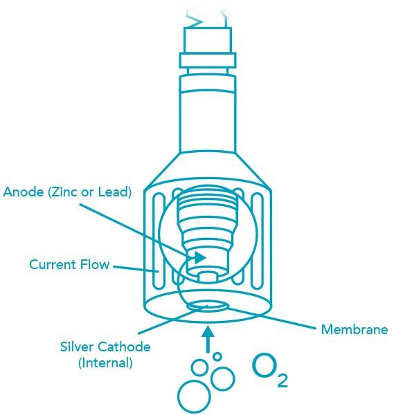
Galvanic DO sensors consist of two electrodes: an anode and cathode which are both immersed in electrolyte (inside the sensor body). An oxygen permeable membrane separates the anode and cathode from the water being measured. Oxygen diffuses across the membrane. It interacts with the probe internals to produce an electrical current (more detail is shown below the DO sensor graphic). Higher pressure allows more oxygen to diffuse across the membrane and more current to be produced. The actual output from the sensor is in millivolts. This is achieved by passing the current across a thermistor (a resistor that changes output with temperature).
V = i * R,
V is output in Volts, i = current
R is resistance from thermistor in ohms
The thermistor corrects for membrane permeability errors due to temperature change. In other words, increasing permeability at higher temperature allows more oxygen to diffuse into the sensor, even though the oxygen pressure has not changed. This would give falsely high DO if the thermistor were not used.
To represent sensor output in ppm or mg/L, the temperature of the water must be known. A separate temperature sensor can be used or one can be built into the sensor. This is independent from the thermistor connected between the anode and cathode to compensate for membrane permeability changes due to temperature change.
Some characteristics of membrane DO probes are:
- The pH of the solution does not affect the performance of membrane probes.
- Chlorine and hydrogen sulfide (H2S) cause erroneous readings in DO probes.
- Atmospheric pressure (altitude above sea level) affects the saturation of oxygen. DO probes must be calibrated for the barometric pressure when reading in mg/l (ppm).
- Membrane thickness determines the output level of the probe and the speed of response to change in DO levels.
- Salinity correction must be made
The cathode is a hydrogen electrode and carries a negative potential with respect to the anode. Electrolyte surrounds the electrode pair and is contained by the membrane. With no oxygen, the cathode becomes polarized with hydrogen and resists the flow of current. When oxygen passes through the membrane, the cathode is depolarized and electrons are consumed. The cathode electrochemically reduces the oxygen to hydroxyl ions:
O2 + 2 H2O + 4 e- = 4 OH-
The anode reacts with the product of the depolarization with a corresponding release of electrons.
Zn + 4 OH- = Zn(OH)42- + 2e-
The electrode pair permits current to flow in direct proportion to the amount of oxygen entering the system. The magnitude of the current gives us a direct measure of the amount of oxygen entering the probe.
Because all of the oxygen entering the probe is chemically consumed, the partial pressure of oxygen in the electrolyte is zero. Therefore, a partial pressure gradient exists across the membrane and the rate of oxygen entering the probe is a function of the partial pressure of oxygen in the air or water being measured.
Since the partial pressure of dissolved oxygen is a function of temperature of the sample, the probe must be calibrated at the sample temperature or the probe’s meter must automatically compensate for varying sample temperature. Note that this thermal effect is different from the thermal response of the membrane discussed above.
The reading of a DO probe must be corrected for the amount of salt in the sample. As seen in the chart below, the salt in solution will reduce the actual concentration of oxygen.
In all DO Probes, the membrane/sample interface should have a few cm/sec flow of the sample for precision performance. Without flow at the interface, the surrounding oxygen will be consumed and the local reading dropped.
The output of the probe increases (up to a point) with relative movement between the probe and sample.
DISSOLVED OXYGEN MEASUREMENT
The amount of oxygen that a given volume of water can hold is a function of the atmospheric pressure at the water-air interface, the temperature of the water, and the amount of other dissolved substances (such as salts or other gases) in the water. Recall seeing bubbles in a pot of water just before it starts to boil. These bubbles are the air which was dissolved in the water at room temperature. When the water boils, the dissolved oxygen is ejected—warmer water contains less DO. When other substances, such as salts, are dissolved in a unit volume of water, there is less room for oxygen to dissolve—oxygen is less soluble than most salts
The following table shows the relationship of dissolved oxygen (mg/L) to temperature and salinity:
Oxygen Saturation Based on Temperature and Salinity
| Temp (deg C) | Salinity (ppt) | |||||
| 0ppt | 9 ppt | 18.1ppt | 27.1ppt | 36.1ppt | 45.2ppt | |
| 0 | 14.62 | 13.73 | 12.89 | 12.10 | 11.36 | 10.66 |
| 10 | 11.29 | 10.66 | 10.06 | 9.49 | 8.96 | 8.45 |
| 20 | 9.09 | 8.62 | 8.17 | 7.75 | 7.35 | 6.96 |
| 25 | 8.26 | 7.85 | 7.46 | 7.08 | 6.72 | 6.39 |
| 30 | 7.56 | 7.19 | 6.85 | 6.51 | 6.20 | 5.90 |
| 40 | 6.41 | 6.12 | 5.84 | 5.58 | 5.32 | 5.08 |
The relationship between temperature, salinity, and dissolved oxygen is approximated with the following exponential equation:
ln( C ) = -139.34 + (1.5757 x 10⁵/T) – (6.6432 x 10⁷/T2) + (1.2438 x 10¹⁰/T3)
– (8.6219 x 10¹¹/T4) – S [1.7674 x 10⁻² – (10.754/T) + (2.1407 x 10³/T2)]
T = Temperature in degree Kelvin
S = Salinity in parts per thousand (ppt)
C = Concentration in mg/L
As the pressure of the air above the water is increased, more oxygen will be dissolved in the water. This increases the concentration of the dissolved oxygen. The solubility of a gas in a liquid is directly proportional to the pressure of that gas above the liquid—Henry’s law. This is often expressed as:
p = k C (C = concentration of DO)
If different gases are mixed in a confined space of constant volume and at a definite temperature, each gas exerts the same pressure as if it alone occupied the space. The pressure of the mixture as a whole is the total of the individual or partial pressure of the gases composing the mixture—Dalton’s law of partial pressures. The partial pressure of each gas is proportional to the number of molecules of that gas in the mixture. Air is 20.948% oxygen. When air bubbled through water, only 20% as much oxygen dissolves as would dissolve if pure oxygen were used instead of air, at the same pressure.
Concentration of dissolved oxygen is also measured in units of % saturation. “% saturation” is simply the ratio of the measured mg/L of dissolved oxygen divided by the mg/L of dissolved oxygen at saturation—as given in the above tables, saturation levels is dependent upon the temperature, salinity, and pressure. Since % saturation is a ratio, it is not affected by these conditions if the calibration at 100% saturation was performed under the same conditions.
Solubility of solutes as a function of temperature (mg of solutes per liter of water):
| Solute | Temperature (Deg C) | |||||
| 0 | 20 | 40 | 60 | 80 | 100 | |
| 02 | 69 | 43 | 31 | 14 | 0 | |
| CO2 | 3350 | 1690 | 970 | 580 | ||
| NaCl | 357,000 | 360,000 | 366,000 | 373,000 | 384,000 | 398,000 |
| KCl | 276,000 | 340,000 | 400,000 | 455,000 | 511,000 | 567,00 |
With stationary, continuously monitoring Dissolved Oxygen Probes, the source of the oxygen being measured is air. Thus, Dissolved Oxygen in air or saturated water (mg/l or ppm) as a function of temperature is determined by:
Solubility (ml/L) x Density (mg/ml) x % in air = saturated DO in mg/L (ppm)
Solubility (mg/L) x % in air = saturated DO in mg/L (ppm)
Increasing temperature usually increases the solubility of solids and liquids whereas it reduces the solubility of gases. Also keep your units straight–mg/L, ppm, ml/L, % saturation.